


Dongguan Leda Metal Co.,Limited
News
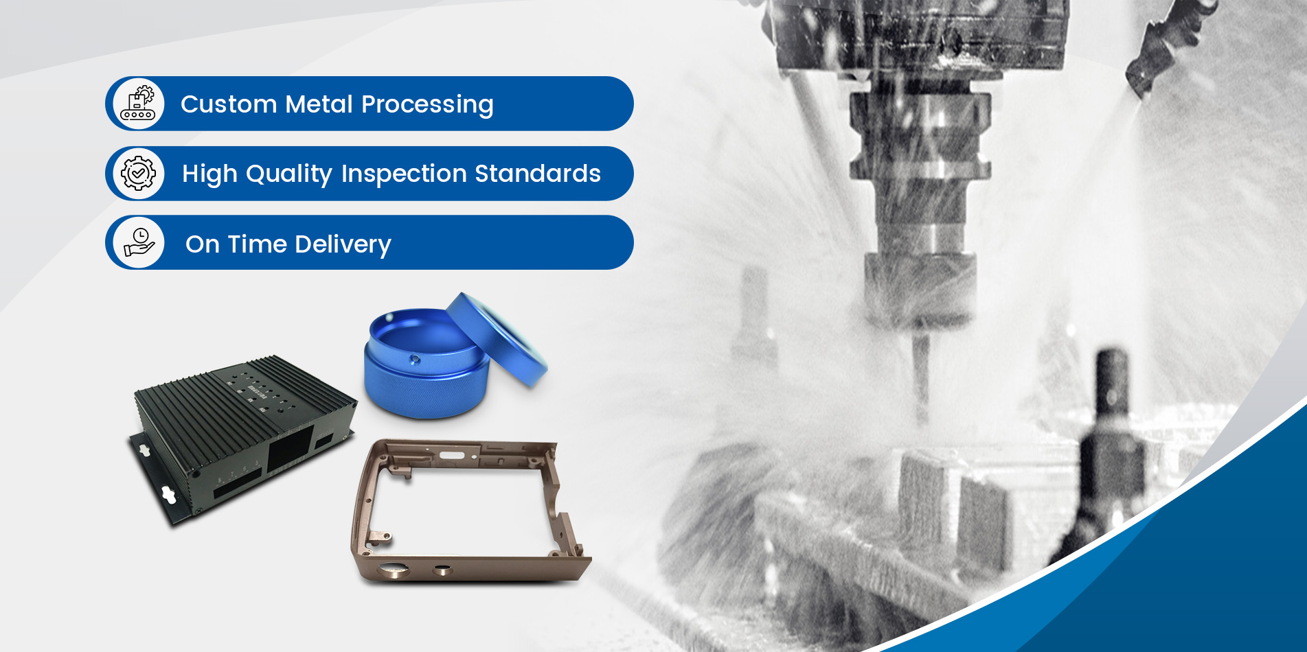
- Custom Aluminum CNC Turning PartCNC Turning/Lathe parts can be divided into many kinds according to the different kinds of lathe, the most common are automatic lathe parts, CNC lathe parts, instrument lathe parts and so on. The metal materials used in Turning lathe parts are copper, iron, aluminum, stainless steel and so on.
2023 10/10
- Customized Metal Stamping ServiceProcess: Metal Stamping Tolerances: 0.02mm Customized: Customized Item Name: Sheet Metal Parts Stamping Metal Parts Size: Customized Machining Processes: Metal Fabrication, Machining Trademark: ACE Transport Package: PP Bag/Carton or According Customers′ Requirement Specification: OEM Parts Origin: China About Us Dongguan Leda Metal Co., Ltd. is a professional manufacturer for OEM parts, including OEM metal stamping, pressing, punching, welding, casting, forging, machining, deep drawn and fabrication products with various surface treatments, etc. With the development, we set up our machining lines in the year of 2009. Our products are exported to USA, Canada, France, Italy, Spain, Holland and other markets, which are used in machining, construction, electronics, furniture, auto industries etc. Product Description: Product Name Metal Stamping Parts, Made of Brass, OEM Orders are Welcome Product Dimension Various shapes are available Product Shape Various shapes are available Processing Type CNC Machining Tolerance as per customers' requirement. Material Standard: ISO, DIN, ASTM, UNS, AISI, JIS, BS, NF Materials available sand casting, investment casting, die casting, permanent mold casting, forging, stamping, welding, and CNC machining Material Thickness as per customers' requirement. Surface Treatment/Finish Anodize, Chromate, Electrolytic Plating, Nickel Plating, Galvanize, Tempered, Paint, Powder Coating, Polish etc., Heat treatment capability Annealing, Normalizing , Nitriding, Tempering ,Carbonitriding capability Carburizing and induction hardening etc., Industry Of Use Used in metallurgy, automobile, aero, chemical, ship hardware, and other industries Quality Assurance ISO 9001:2008, ISO/TS 16949:2009, RoHS Sample Lead-time Within 1day for samples available from our stock About 1-2weeks for custom samples Mass Production Lead-time 3-7 weeks after receiving deposit. Price Terms: EXW/FOB/CFR/CIF Shanghai or any other airport or seaport, China Payment Terms 30% deposit, balance against B/L copy Modification Mould modification until the customers satisfy it. Inspection In-house or third party, all the products are strictly inspected by skilled QC Design: We use the most advanced mould design software Auto CAD, Pro/E, Solidworks, UG (dwg, dxf, IGS, STP, X-T) Country of Origin China (mainland) Main Export Markets Europe, America, Mid East, Asia, Africa etc., Service Type: OEM & ODM Business Type: Manufacturer, Exportor Advantages Expert in producing OEM parts: metal stamped, machined, deep drawn and sheet metal formed parts with various finishing Geographical location advantage: Our factory is in Guangdong which can help us to offer better services for the customers from all over the world Our factory nearby Guangzhou and Shenzhen ports, which can save transportation time and cost Employing reliable rockers and utilizing advanced machines: we have a full range of machinery and equipment for punching, welding, CNC, milling and grinding. We also have experienced technicist who are engaged in technical development. Our skilled workers, professional engineers, R and D center and excellent foreign trade team always keep the passion to support our customers
2023 09/12
- CNC machining process designThe design of the numerical control processing route must be fully considered. Attention should be paid to the correct division of the process, the rational arrangement of the sequence, and the convergence of the numerical control machining process and the ordinary process. 1. Division of processes Compared with the processing of CNC machine tools and ordinary machine tools, the machining process is more concentrated. According to the processing characteristics of CNC machine tools, the division of machining processes can be done in the following ways: 1) According to the clamping positioning division processThis method is generally adapted to the processing of a small number of parts, mainly the processing site is divided into several parts, each process processing part of it. For example, when machining the shape, the inner cavity is used for clamping; when the inner cavity is machined, the outer shape is clamped. 2) Divide the process by the tool usedIn order to reduce the number of tool changes and idle time, you can use the principle of tool concentration to divide the process, use a knife in a fixture to complete all processing parts that can be processed, and then change the second knife to process other parts. This method is mostly used on special CNC machine tools or machining centers. 3) Dividing processes by rough and fine processingFor parts that are prone to machining deformation, taking into account the machining accuracy, deformation and other factors of the workpiece, the process can be divided according to the principle of rough and fine processing separation, that is, after the first rough finish.In the process division, it is necessary to be flexible in accordance with the structural requirements of the workpiece, the installation method of the workpiece, the processing technology of the workpiece, the performance of the CNC machine tool, and the factory production organization and management, and strive to be reasonable. 2. Arrangement of processing sequence The arrangement of the processing sequence shall be based on the structure of the workpiece and the condition of the blank, and the positioning and installation of the workpiece shall be selected to ensure that the rigidity of the workpiece is not destroyed and the deformation is minimized. Therefore, the arrangement of the processing sequence shall follow the following principles: 1) The processing of the previous process cannot affect the positioning and clamping of the next process 2) Processing the outer contour of the workpiece after machining the inner cavity of the workpiece first 3) Minimize repeat positioning and tool change times4) In a multi-step process of installation and processing, the process of rigidly destroying the workpiece is arranged first. 3. The connection between CNC machining process and common process As the NC machining process is interspersed throughout the entire process of the workpiece processing, each process needs to establish state requirements, such as the allowance of the machining allowance, the precision and tolerance of the positioning surface and hole, and the technical requirements of the orthopedic process. For heat treatment of blanks, various processes must be considered before and after. 4. Design of CNC machining process and processing route The main task of CNC machining process design: determine the specific processing content, cutting amount, process equipment, positioning and installation methods and tool movement trajectory of the process, in order to prepare the program. Among them, the setting of the processing route is a very important link. The processing route is the movement path of the tool location relative to the workpiece during the cutting process of the tool. It not only includes the contents of the machining process, but also reflects the arrangement of the processing sequence. Therefore, the processing route is The important basis for the preparation of processing procedures. 1) The principle of determining the processing route 1 The processing route should ensure the accuracy and surface roughness of the workpiece being machined. 2 Design and processing routes should reduce idle travel time and improve processing efficiency. 3 Simplify numerical calculations and reduce program sections, reducing programming workload. 4 According to the shape of the workpiece, stiffness, allowance, machine tool system stiffness, etc., determine the number of cycles of processing. 5 Reasonably design the cutting and cutting direction of the tool. Unidirectional approach to positioning is used to avoid positioning errors caused by the backlash of the transmission system. 6 Reasonably choose milling milling or milling in the milling process. In general, CNC machine tools use ball screw, the movement clearance is very small, so the advantage of milling is more than the milling. 2) CNC machining process1 CNC lathe processing routeCNC lathe turning processing line shown in Figure 1 AB-0p-D, where A is the tool change point, B is the entry point, C-0p is the tool cutting path, 0p is the cut-out point, D is the retract point. 5. Workpiece installation and fixture selection 1) Installation of the workpiece 1 It strives to meet the basic unity principle of design basis, process standard, installation datum, and workpiece coordinate system. 2 Decrease the number of mountings, and make it possible to machine all surfaces to be machined after one set-up.3 Use special fixtures as much as possible to reduce the time taken to install and adjust the machine. 2) Selection of fixturesAccording to the processing characteristics of CNC machine tools, coordinate the three relationships between the fixture coordinate system, the machine coordinate system and the workpiece coordinate system, in addition to the following points: 1 Process parts in small batches and use combination fixtures, adjustable fixtures, and other universal fixtures as much as possible. 2 Batch production considers the use of special fixtures for easy loading and unloading. 3 The positioning of the fixture and the components of the clamping mechanism do not affect the movement of the tool. 4 The loading and unloading of parts should be convenient and reliable. Batch production can use pneumatic clamps, hydraulic clamps and multi-station clamps.
2023 08/18
- CNC machining tool selectionCNC machining tool selection When programming, it is important to choose the CNC tool correctly. The general requirements for CNC tools are easy installation and adjustment, good rigidity, high precision, and good durability. Based on this, the cutting performance of the workpiece material, the machining capability of the machine tool, the type of CNC machining process, the cutting amount, and the machine tool are taken into consideration. Numerous factors related to the working range of the numerical control device. 1. Factors Affecting CNC Tool Selection When selecting the type and size of the tool, the following factors are mainly considered: (1) Production properties The production property here refers to the batch size of the parts, mainly considering the influence on the tool selection from the processing cost. For example, when special tools are used in mass production, it may be cost-effective. In single-piece or small-batch production, selecting a standard tool is more appropriate. (2) Machine type The effect of the CNC machine used to complete the process on the type of tool selected (drill, lathe, or milling cutter). High-productivity tools such as high-speed cutting tools and large-feed tools can be used under conditions that ensure the rigidity of the workpiece system and the tool system. (3) CNC machining program Different CNC machining programs can use different types of tools. For example, holes can be machined using drills and reamers, as well as drills and boring tools. (4) The size and shape of the workpiece The size and shape of the workpiece also influence the choice of tool type and specification. For example, the special surface must be machined with a special tool. (5) Surface roughness The roughness of the machined surface affects the structural shape of the tool and the amount of cutting. For example, rough roughing cutters can be used for roughing, and fine-tooth milling cutters are preferred for fine milling. (6) Processing accuracy The machining accuracy affects the type and shape of the finishing tool. For example, the final machining of the hole can be processed by drilling, reamer, reamer or boring tool. (7) Workpiece materials The material of the workpiece will determine the choice of tool material and geometric parameters of the cutting part. The tool material is related to the machining accuracy of the workpiece and the hardness of the material. 2. CNC tool performance requirements Because the numerical control machine tool has the characteristics of high processing precision, high processing efficiency, centralized processing procedures and fewer parts clamping times, higher requirements are placed on the used CNC tool. In terms of tool performance, numerical control tools should be higher than those used by ordinary machine tools. When selecting a numerically controlled tool, the first priority should be to use a standard tool, and when necessary, various high-efficiency compound tools and special special tools can be selected. When selecting the standard CNC tool, it should be combined with the actual situation, as far as possible the use of various advanced tools, such as indexable tools, solid carbide tools, ceramic tools and so on. When choosing CNC machine tools, you should also consider the following issues: (1) The types, specifications, and accuracy grades of CNC tools should be able to meet the machining requirements. The tool material should be compatible with the workpiece material. (2) good cutting performance. In order to adapt the tool to rough cutting or machining of difficult-to-machine materials, the tool can adopt a large amount of back-feed and high feed. The tool should have the ability to withstand high-speed cutting and strong cutting. At the same time, the same batch of tools must be stable in terms of cutting performance and tool life, in order to achieve tool change by tool life or by the numerical control system tool life management. (3) High precision. In order to meet the requirements of high-precision CNC machining and automatic tool change, the tool must have high precision. For example, the integral end mill has a radial dimension accuracy of up to 0.005mm. (4) High reliability. To ensure that the accidental damage and potential defects of the tool will not be affected in the NC machining process, the cutting tool and its associated accessories must have good reliability and strong adaptability. (5) High durability. CNC machining tools, whether roughing or finishing, should have a higher durability than the tools used in ordinary machine tools in order to minimize the number of times to replace or grind tools and tools, thereby improving the machining efficiency of CNC machine tools. And ensure the quality of processing. (6) Good chip breaking and chip removal. In NC machining, chip breaking and chip evacuation are not handled in time as in the case of ordinary machine tools. Chips are easily wound on the tools and workpieces, which can damage the tool and scratch the workpiece surface, and even cause injuries and equipment accidents. Affects the processing quality and the safe operation of the machine tool, so the tool is required to have better chip breaking and chip removal performance. 3. Tool selection method The choice of tool is one of the important contents in the numerical control processing technology. It not only affects the machining efficiency of the machine tool, but also directly affects the machining quality of the part. Because the spindle speed and range of CNC machine tools is much higher than that of ordinary machine tools, and the spindle output power is larger, compared with the traditional processing methods, higher requirements are put forward for CNC machining tools, including high precision, high strength and rigidity. Good, durable, and requires a stable size, easy installation and adjustment. This requires a reasonable tool structure, standardization of geometric parameters, and serialization. CNC tooling is one of the prerequisites for improving the machining efficiency. Its choice depends on the geometry of the part being machined, the state of the material, the fixture and the rigidity of the tool selected by the machine tool. The following should be considered: (1) Select the tool according to the cutting performance of the part material. Such as car or milling high-strength steel, titanium alloy, stainless steel parts, it is recommended to choose a good wear-resistant indexable carbide cutting tools. (2) Select the tool according to the machining stage of the part. That is to say, the roughing stage is mainly based on removing the margin, and the tool with better rigidity and lower precision should be selected. The semi-finishing and finishing stages are mainly used to ensure the machining accuracy and product quality of the part. The high durability and accuracy should be selected. For high cutting tools, the accuracy of the tools used in the roughing stage is the lowest, and the accuracy of the tools used in the finishing stage is the highest. If the same tool is used for rough and finish machining, it is recommended to use the tools that are eliminated during the roughing process because the wear of the tools that are eliminated during the finishing process is mostly due to slight wear of the blades, the wear of the coating is lighted, and the continued use will affect the finish machining. Processing quality, but less impact on roughing. (3) Select tools and geometric parameters according to the characteristics of the processing area. When the part structure allows, a tool with a large diameter and a small aspect ratio should be selected; the center-end angle of the over-center milling cutter for cutting thin-walled and ultra-thin-wall parts should have enough tangential angle to reduce the cutting of the tool and the cutting part. force. When processing aluminum, copper and other softer material parts, choose an end mill with a slightly larger front rake and do not use more than 4 teeth. When selecting a tool, the size of the tool must be adapted to the surface dimensions of the workpiece being machined. In production, the peripheral contours of plane parts are often machined with end mills. When milling planes, hard alloy insert milling cutters are selected. When machining bosses and grooves, high-speed steel end mills are selected; surface roughing or rough machining is performed. In the case of holes, corn milling inserts with carbide inserts can be selected. For the machining of some three-dimensional profiles and variable bevel outlines, ball-end cutters, ring cutters, taper cutters, and disc-type cutters are often used. In the free-form surface machining, since the cutting speed of the end of the ball-end tool is zero, in order to ensure the machining accuracy, the cutting spacing is generally very small, so the ball-end milling cutter is suitable for the surface finishing. The end mill is far superior to the ball end mill both in terms of surface machining quality and machining efficiency. Therefore, in the premise of ensuring that the parts are not over-cut, the rough end and semi-finishing surfaces are selected as much as possible. Milling cutter. In addition, the tool's durability and precision are highly related to the tool's price. It must be noticed that, in most cases, selecting a good tool increases the tool cost, but the resulting increase in machining quality and machining efficiency. , you can greatly reduce the cost of the entire process. In the machining center, all the tools are pre-installed in the magazine, and the corresponding tool change actions are performed through the NC program's tool selection and tool change commands. The corresponding standard tool holders suitable for the machine tool system specifications must be selected so that the tools for NC machining can be quickly and accurately mounted on the machine tool spindle or returned to the tool magazine. The programmer should be able to understand the structure of the shank used in the machine tool, adjust the method and adjust the scope of the content in order to ensure the radial and axial dimensions of the tool in the programming, a reasonable arrangement of the order of the tool.
2023 07/12
- Basic knowledge of CNC MACHINING Chapter 3.Continuing with the content of the previous chapter, we will continue to introduce cnc milling related technologies today Eight. Feed servo axis control The feed of the machine tool table (including the turntable) is driven by a servo mechanism, which is currently electrified and driven by a servo motor, and most of them use a synchronous motor. The motor is directly connected to the ball screw (as shown in the figure below), so that due to the short transmission chain, the loss of motion (lost motion) is small, and the response is fast, so high precision can be obtained. The feed servo of the machine tool belongs to the position control servo system. As shown in the figure below, the input terminal receives the position pulse serially output from the CNC interpolator in each interpolation cycle. The number of pulses indicates the amount of movement of the position (usually a pulse is 1 μm---that is, the resolution of the system is 1 μm); the frequency of the pulse (that is, the number of pulses output per unit time) indicates the speed of feed ; The symbol of the pulse indicates the feed direction of the axis, usually the pulse is directly sent to the command input ports of different servo axes. The figure below only shows one feed axis. The actual machine tool has several axes, but the control principle is the same. When several axes receive interpolation commands in the same interpolation period, due to the different feed amounts, feed speeds, and motion directions at the same time, the resulting motion is a curve, and the tool moves according to this curve. The workpiece contour required by the program can be processed. The requirements for feed servo are not only static characteristics, such as: positioning accuracy and stability when stopping. More importantly, the feed servo has good rigidity, fast response, good motion stability and high resolution. In this way, high-quality workpieces with smooth surfaces can be processed at high speed and high precision. 1. The structure type of the servo system The servo system is divided into open-loop and closed-loop structures. open loop: The so-called open loop is a servo system without position feedback. The electrical system of this structure is driven by a stepper motor. Since there is no feedback of speed and position, the following accuracy is poor and the responsiveness is poor, so the machining accuracy is poor and the efficiency is low. closed loop: A closed loop is a servo system with position feedback of the controlled element. The composition of the system includes: executive element------servo motor (generally directly connected with the ball screw); speed controller and position controller, the position controller receives the output command of the CNC interpolator 2. Synchronous motor The electrical system of the closed-loop servo structure is currently driven by an AC servo motor, and most of them use a permanent magnet synchronous motor. The structure of the permanent magnet synchronous motor is shown in the figure below. The rotor is a magnetic pole made of permanent magnetic steel with high magnetic permeability, with a motor shaft in the middle, and the two ends of the shaft are supported by bearings and fixed on the casing. The stator is a magnetic conductor made of silicon steel sheets. The inner surface of the magnetic conductor has tooth grooves, and the three-phase winding coils wound with wires are embedded. In addition, an encoder is installed at the rear end of the shaft. When the three-phase winding of the stator is supplied with three-phase alternating current, the generated space rotating magnetic field will attract the magnetic poles on the rotor to rotate synchronously. The speed control and electric power supply of synchronous motors use inverters. In the inverters, the power drive circuit elements that change from DC to three-phase AC need to commutate in real time according to the position of the rotor magnetic field, which is very similar to that of DC motors. The commutation of the rotor winding current with the position of the stator field. Therefore, in order to detect the position of the rotor magnetic field of the synchronous motor in real time, an encoder (optical code disc ------ 11 in the figure) is installed on the motor shaft (rear end). Thanks to the optical code disc, no matter the speed of the motor is fast or slow, the position of the magnetic pole magnetic field on the rotor can be actually measured along with the rotation of the motor shaft, and the position value can be sent to the control circuit so that the controller can The commutation of the power components of the inverter is controlled in real time, and the self-controlled commutation of the servo drive is realized. Therefore, some people call the drive controller and motor of this synchronous motor a self-commutating synchronous motor; in addition, because its control characteristics are similar to a DC motor, it is also called a commutator-free DC motor. Linear motor: In order to increase the movement speed of the worktable, increase the acceleration, simplify the transmission chain, and thereby improve the transmission accuracy, a linear motor has recently appeared. This kind of motor is a direct-connected motor, that is, it is directly installed on the linear motion table. 3. Position sensor and speed sensor Photoelectric encoder: The encoder is a measuring element for rotary motion, usually installed on the motor shaft or ball screw, and the physical quantity it directly measures is the angle at which the motor or screw rotates. There are two types of encoders: incremental measurement or absolute measurement. Linear encoders: Currently, linear encoders are used to measure the position or displacement of linear moving parts. There are transmission scales using glass and reflection scales using metal substrates. The working principle is similar to that of a photoelectric encoder. The transmissive grating ruler is easy to install and is directly mounted on the side of the workbench, so it is used more often. 4. Servo drive The amplifier (driver) that controls the operation of the synchronous servo motor is an AC inverter. FANUC divides the amplifier into two modules: rectifier power supply module (PSM) and servo inverter module (SVM) Nine. Spindle drive control 1. control block diagram Spindle control is mainly speed and motor speed control. In the program, use the command: S and the five-digit value to command the rotation number of the spindle. For example: S1200; means that the spindle is required to rotate at 1200 rpm. The commands for forward and reverse rotation are M03 (forward rotation); M04 (reverse rotation). In order to detect the rotation speed of the spindle, a speed sensor is installed on the spindle or the spindle motor. 2. Spindle speed sensor and position sensor Only speed control without position feedback loop. The speed measurement and feedback of the spindle motor uses a magnetic sensor mounted on the spindle motor shaft. As shown below. As the spindle motor turns, the sensor sends out 128, 256, 384 or 512 pulses (depending on the model of the motor) per revolution to count the number of revolutions of the spindle motor. If the motor and the main shaft are not 1:1 coupled, a position encoder must be installed on the main shaft, and the number of rotations of the main shaft is measured with a one-turn signal from the encoder. Usually this kind of encoder is photoelectric, and it sends out 1024 pulses per turn, and also sends out a one-turn signal. This encoder can be used to realize thread processing and rigid tapping and spindle orientation during tool change of machining centers 3. Spindle motor There are two types of motors used for spindle drive. Type: asynchronous motor and synchronous motor. The asynchronous machine is easy to manufacture, has high reliability, and has good high-speed operation performance, so FANUC uses an asynchronous machine. The synchronous machine has good low-speed performance, good controllability, high torque at low speed, and a wide range of constant power speed regulation is easy to achieve. Generally, asynchronous motors are generally used for processing aluminum and light metal parts with high spindle speed. The spindle speed for processing cast iron or steel parts is low, and some processing methods (such as Cs axis method) also require large torque at low speeds, so synchronous motors tend to be used. Especially recently, in order to improve the machining accuracy, the mechanical design makes the drive motor directly connected to the main shaft of the machine tool, so the development of synchronous machine as the drive of the main shaft, especially the built-in main shaft motor, often uses the synchronous machine. If you need more learning materials, the 373600976 group can help you 4. Spindle Motor Drive Amplifier The control of the spindle motor is similar to the servo motor described above. But usually there is only speed control, so there is no need for a position loop. The figure below is a block diagram of the FANUC spindle motor driver. Divided into two modules: PSM and SPM. PSM is a power supply module, which, like the feed servo drive, converts the input AC power supply into a DC power supply to supply power to the inverter. SPM is the inverter part, which converts the DC power into three-phase AC to supply power to the stator of the motor. ten. Control of external axes Use servo motors to control the actions of auxiliary mechanical equipment on or outside the machine tool, such as: tool changing manipulator, changing worktable, loading/unloading, workpiece or blank handling. Power Mate i is a position motion controller, which controls the independent movement of each axis or coordinated movement in time, so that an axis moves to a certain position or a certain distance at a certain speed. However, there is no positional dependency between them, that is, the system does not need to have the function of a positional interpolator. Of course, FANUC's Power Mate i D has a two-axis linkage interpolator, which can be used according to actual needs.
2023 04/08
- Basic knowledge of CNC MACHINING Chapter 2.Welcome to the second chapter of basic knowledge of machine tool CNC. In the previous chapter, we introduced the basic equipment and parameter knowledge of cnc. In this chapter, we will show how the cnc machine works. Information and data input and output control The input information and data of CNC include processing program, function parameter, system parameter, machine tool parameter, servo control parameter, spindle control parameter, PMC parameter, tool data, Macro (macro) variable, coordinate system, special software data...these information and Data is input or output by the information input/output operation device through the corresponding data port. 1. Data input and output equipment Currently commonly used I/O equipment in CNC systems are: ⑴. Keyboard: In order to reduce the installation size, it is usually specially designed, called MDI keyboard, to input information and data to CNC for operating CNC unit . ⑵. Machine tool operation panel: various actions of the operator operating the machine tool. ⑶. PC. ⑷. Floppy disk drive (Handy file): FANUC system dedicated equipment. ⑸. Panel-i: Special equipment for FANUC system. ⑹. Flash memory card and so on. If you need more learning materials, the 373600976 group can help you Each device has a corresponding driver and control program. 2. Data input and output port The CNC controller is equipped with several data transmission ports for connection with external data devices. ⑴. RS-232C port: Connect to PCs, floppy disk drives and other devices with serial communication ports. ⑵. HSSB: High-speed serial data bus, used to connect with PC or Panel-i, and transmit data at high speed. ⑶. I/O Link: It is a data port based on RS-485, which is a Japanese industrial enterprise standard, and is used to transmit I/O signal information for strong point control of machine tools. ⑷. Ethernet. ⑸. On-site local network. Regarding ⑷ and ⑸, it will be specifically described below. 3. monitor It is used to display the status and results of the operation and operation of the system, and to display the processing simulation graphics. The current FANUC system has all used LCD monitors. This kind of display is small in size, the color of the color display is rich, and the simulation of the workpiece is very realistic. six. Centralized control of network and CNC processing The network of the mechanical processing plant can generally be divided into three levels: the factory level network; the processing unit level network and the lower field network; the factory level and the processing unit level network currently use Ethernet. Processing site network, FANUC system can be equipped with: Profibus-DP; Device net; FL-Net. Different networks need to be equipped with different network boards 1. ethernet FANUC CNC-16i/18i/21i, 0i-C can be equipped with 3 Ethernet ports for different purposes: the built-in Ethernet port of the CNC main board, the network board and the network card. Among them, the network card is plug-and-play for temporary use, Such as debugging the ladder diagram; debugging the feed servo characteristics and spindle characteristics of the machine tool.... The network board is a board added to the system, and has a large-capacity semiconductor memory (up to 1GB) instead of a hard disk. It is mainly used to connect with large-capacity data equipment (such as PC) and transfer data and information in batches, such as for mold processing. The built-in Ethernet port on the motherboard can be used for unit control and connected to the unit control host. 2. Live Network The field network is used to batch transmit I/O control signal information with other devices. For example, in an automatic production line, it communicates with information (signals) of other special processing machinery, loading/unloading machinery, material handling machinery, cleaning machinery, etc. Profibus-DP, Device-net or FL-net can be selected according to requirements or regions. FANUC produced these network boards and developed corresponding supporting software. 3. Centralized Control of CNC Machining Modern mechanical processing factories (such as automobile engine manufacturing plants) use CNC machine tools not only to make them run alone, but also to combine multiple CNC machine tools and related special equipment such as loading/unloading devices, material conveying machinery, cleaning machines, turning machines, measuring machines, etc. Machines, special processing machines, etc. are connected into an assembly line. These machines are connected with a network, and the centralized management of production is carried out with a computer. The basis of the centralized production management of the entire factory is the centralized control of the processing units. Processing unit controller: a host computer centrally controls the operation of multiple CNC machine tools. The host computer and CNC system are connected by Ethernet. In order to realize the centralized control of multiple CNC machine tools, the main computer controlling the processing unit must be able to obtain various information and data of each CNC machine tool, including: ①. The operating status of the machine tool: whether it is in processing operation or standby; whether there is an alarm; Which program to process? Which program segment? Is this processing task over? --.②. The information and data of CNC and machine tools, such as: processing program stored by CNC; processing program running on the machine tool; tool information stored by CNC; tool number on the spindle; number of processed workpieces; processing time; program running time; CNC parameters; servo parameters; spindle parameters; machine parameters; PMC parameters; PMC ladder diagram; macro variables; alarm numbers and information, etc. That is to say, the main computer can monitor the operation of each CNC machine tool in real time status, for information on performing maintenance on the machine tool. In addition, the main computer must also: ①. Necessary and sometimes real-time control of each machine tool. For example, the pause and emergency stop of the machine tool; ②. The download of information and data, such as: processing operation instructions; the number of workpieces to be processed; processing programs; tool information; CNC parameters; servo parameters; spindle parameters; machine parameters; PMC parameters ; Ladder diagram of PMC; macro variables and so on. ③. CNC machine tool maintenance and repair guidance information. End users can develop centralized control software (including production management, planning and scheduling, processing site monitoring, fault diagnosis, etc. software) on the main computer controlled by the unit. The basis for the development of these application software must use the CNC information library and communication software package provided by the manufacturer of the CNC system. FANUC has developed tool software FOCAS (FANUC Open CNC Application Software) for this purpose. Using the instructions provided by the software package, the user can realize the communication between the host computer and CNC, and transmit the information and data mentioned above up/down. For the convenience of users, FANUC has also developed a cell controller - i-CELL as a commodity. The figure below is the functional block diagram of i-CELL. If the PMC used by CNC is SB7, it can also transmit and display (on the host computer) the ladder diagram of the controlled machine tool. If you need more learning materials, the 373600976 group can help you seven. Powerful Electric Control of PMC and Machine Tools Start and stop of machine tools; start and stop of spindle; start, end and stop of processing; start and stop of lubrication and cooling; loading and unloading control of workpiece; tool finding and changing; table exchange; start and stop of auxiliary machines , Stop, etc. These machine tool actions are all executed by contactors, relays, and valves. The control signals for instructing these actions have a certain order or timing among each other, and are interlocked with each other. Because of the simple operation of ordinary machine tools, it is realized by hard wiring of electrical elements and components (buttons, keys, contacts, coils, etc.) according to the schematic diagram of relay logic, so it is unreliable to operate. CNC machine tools are controlled by PMC logic. PMC is actually PLC (programmable logic controller.) But because FANUC's machine tool control PLC is specially used to control machine tools, there are many special instructions in it, so it is called PMC----programmable machine tool controller. Moreover, the program format FANUC of PMC uses a ladder diagram. The display format of the ladder diagram is very similar to the relay logic diagram of the machine tool, which is intuitive and easy to understand, edit and operate. As soon as the CNC starts, the PMC program runs. When the CNC executes the machining program, the PMC runs in parallel with the machining program. The PMC scans the input signal of the machine tool or machine operator and the execution result of the control signal of the strong electric cabinet at all times. To perform various actions on the above machine tool, it is necessary to compile control commands in the processing program: M (miscellaneous function), T (tool change), B (second auxiliary function). 1. Signals and their addresses PMC divides the signal into 4 types according to its action part and action direction. If you need more learning materials, the 373600976 group can help you X: Input from machine tool to PMC. Such as: the operator inputs the button, key and switch signal on the machine operation panel. Y: The signal output from the PMC to the machine tool to make the machine tool power-on. Such as: forward and reverse of the spindle; lubrication and cooling on/off signal. The PMC processes the ladder diagram program and outputs these signals to make the machine tool move. G: Signal output from PMC to CNC (CNC input). Some of these signals start a subroutine of the CNC. These subroutines are part of the CNC control software: The strong current control function of the machine tool is designed according to the actual action of the machine tool. Such as: emergency stop (G8.4); automatic processing program start (G7.2); working mode selection (G43.0~2) other signals are PMC to notify CNC to make CNC change or execute a certain operation. Such as: FIN (G4.3) ----It is the PMC notifying the CNC that the auxiliary function M or the tool change function T has finished executing. After CNC receives the signal It can start the execution of the next processing block; *SSTP (G29.6): the control signal for CNC to stop the spindle motor. F: The signal output from CNC to PMC. Some of these signals are signs reflecting the running state of the CNC, indicating that the CNC is in a certain state. like: AL (F1.0): Alarm state. MV(F102): The feed axis is moving. Other signals are the results of executing a certain operation after CNC responds to X (through G), and are used to notify PMC. The PMC receives the signal and handles it appropriately depending on the specific situation. There are also some signals that are the decoding output of the processing program instructions. Such as: M code (F10~F13); T code (F26~F29). CNC outputs these signals to PMC for processing. The above-mentioned signals must be assigned addresses in the ladder diagram program. The addresses of G and F signals are specified by CNC system software and are fixed. Some X signal addresses are also specified by CNC. CNC provides address table. The Y signal can be specified by the PMC designer. The X and Y signals are connected to the CNC unit by the input/output module through the I/O Link port of the CNC. The other ends of the X and Y signals are connected to electrical components through cables. 2. Internal registers When compiling PMC programs, in order to save data or signals, PMC uses some internal registers: R, K, D, T, C, and A. R: intermediate register. Can be used freely. K: Holding register. Stored content is maintained by a backup battery. There are several memory cells already used by the PMC system. D: data memory. Such as storage tool table; speed table of each gear for spindle speed change. T: Timer. Store timer time. C: Counter. Store the preset value of the counter, the count value. A: Display information: store information characters. 3. Function instructions To compile the PMC (PLC) control logic of a machine tool, it is first necessary to clarify the controlled (to be realized) machine tool action, and arrange the timing of each detail of the action, that is, the step-by-step sub-steps (subtle actions) that will realize the action ) List the sequence table in order, estimate the execution time of the necessary steps, consider the relationship between actions, the interlocking and unlocking conditions between actions, and understand the implementation of various subtle actions and execute PMC instruction for electrical components. PMC logic is to use PMC instructions (language) to express the execution of these subtle actions in sequence. For sequential logic programs, different system manufacturers provide different formats, commonly used are: statement list and ladder diagram. FANUC's PMC logic program uses the ladder diagram format, which is characterized by intuition, similar to the relay logic diagram of the machine tool, so it is very easy to understand. Moreover, the PMC language uses many special-purpose instructions, called functional instructions. In this way, the logic diagram is compiled quite concisely. There are about 50 functional instructions of FANUC PMC, but about 20 are actually commonly used, such as: timer, counter, rotation instruction, decoder, etc. The following two pictures are the functional instruction format and the functional instruction set (partial). 4. Ladder diagram 5. Execution of PMC After the CNC is turned on, the CNC and the PMC run simultaneously. If the PMC receives the X signal from the machine operator to request the CNC to perform a certain operation, such as starting an automatic machining program, the X signal will be sent to G7.2 in the ladder diagram, and the CNC will know that it is to execute the automatic cycle Start a subroutine, that is, execute it immediately. Output F0.5 during execution to notify PMC that CNC is running the machining program. If the CNC finds M, T and other commands in the program segment when executing the processing program, it will decode the command and send it to the PMC with the F signal address, for example: M code, send it to F10~F13. After PMC processing (decoding, sequence and interlocking), it is sent to the power cabinet through a certain Y address, and the required control actions are performed by the actuator (relay, etc.). If there is a feed axis motion command in the part processing program block where the M command is located, after the controlled axis has completed the required movement amount, it is necessary to judge whether the PMC has executed the action assigned by the CNC (command), so the PMC is required When executing commands such as M and T, a completion signal FIN must be returned. When CNC receives this signal, it can read the next block and execute the next block.
2023 04/05
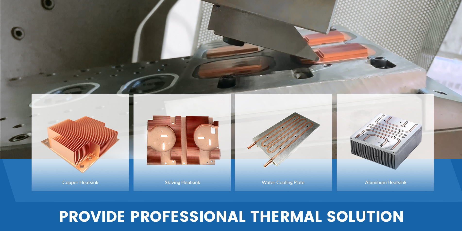
- Aluminum profile heat sink product characteristics and application fieldsAluminum heat sink is also called radiator profile, or sun flower heat sink. Aluminum heat sink has the features of appearance bleaching, light weight, good heat dissipation function and good energy saving effect. The surface of the processed aluminum profile radiator is treated by anodizing to increase the corrosion resistance of the aluminum. Wear resistance and surface beauty. At present, the commonly used types of radiator aluminum profiles are: electronics, electrical appliances, computer radiator aluminum profiles, solar flower aluminum profiles, power semiconductor radiator profiles, etc. Aluminum radiator is widely used in: machinery, cars, wind power generation, construction machinery because of its superior function. Air compressor, railway locomotive, household appliances and other occupational categories. Aluminum profile radiators mainly have high - pressure casting aluminum and tensile aluminum alloy welding two. Its advantages are: (1) The heat dissipation of aluminum radiator is better, the characteristics of energy saving is very significant, in the same room, if the same standard radiator is used, the number of aluminum cast pieces is less than steel (2) The corrosion resistance of aluminum radiator is good, without adding any additive. The principle is that once aluminum meets oxygen in the air, the surface will generate a layer of oxide film, which is both tough and fine, to avoid further corrosion of the body.
2023 04/03
- The difference between sheet metal parts and stamping parts?The technological process is as follows: Sheet metal parts are mainly bent with sheet metal, the use of the machine is mainly bending machine, parts are relatively large, the process is generally: plate cutting (blanking) - bending - welding. The machine used for stamping parts is the punch press. The precision of the parts should be high. Generally, the punching mold should be used to ensure the punching mold. Process: cutting plate (blanking) - punching - deburring. The differences between sheet metal parts and stamping parts are as follows: 1. Different quantities Sheet metal is hand plate or small batch production. Accurately speaking, it is proofing, and then the quantity is relatively small, if the mold is opened, the cost of the mold can not earn back. Stamping, is the mass production and precision requirements of things, the output is larger, it is sure to open the mold stamping. 2. Different processes Sheet metal parts are metal sheet parts that are manually beaten by workers with simple equipment such as hammers. Characteristic is low efficiency, parts quality through manual control, not stable, but low cost, used for small batch life, or trial production stage. Stamping parts are metal sheet parts that are stamped by die and press. It is characterized by high efficiency, parts quality controlled by mold, strong stability, but high cost, used for mass production. 3. Different procedure Stamping parts rely on press and mold to impose external force on plate, strip, pipe and profile, so as to produce plastic deformation or separation, so as to obtain the required shape and size of the workpiece forming processing method. Stamping and forging belong to plastic processing, collectively known as forging. The blanks for stamping are mainly hot and cold rolled steel plates and strips. Sheet metal is a comprehensive cold working process for sheet metal, including cutting, punching/cutting/compounding, folding, welding, riveting, splicing, forming, etc. Its remarkable feature is the same thickness of the same parts. The products processed by the sheet metal process are called sheet metal parts. The sheet metal parts referred to in different industries are generally different, and are mostly used for assembly.
2023 02/13
- Basic knowledge of CNC MACHININGBasic knowledge of CNC MACHINING. 1. CNC machine tool and CNC system CNC means computer digital control. 1. CNC machine tool ⑴. For metal cutting Hole processing, tapping, boring, milling, turning, thread cutting, plane cutting, contour processing, surface grinding, cylindrical grinding Cutting, internal grinding, etc. (2) Wire electrode cutting machine. (3) Punch, step punching, stamping, metal forming, bending and other machine tools. (4) Industrial robots. (5) Injection molding machine. (6) Detection and measuring machine. (7) Woodworking machinery. (8) Special material processing machinery: such as processing stone, glass, radioactive mineral aggregate, etc. (9) Special processing machinery Laser processing machine, gas cutting machine, welding machine, drawing machine, printing machine, etc. With the development of electronic technology, computer technology and IT technology, at present, these machine tools and processing equipment can be controlled by numerical computer with numerical data, which is called CNC control. Need more learning materials. Group 373600976 can help you 2. CNC system CNC system means computer numerical control system. Basic configuration of CNC system CNC control of machine tools is a multidisciplinary integrated control technology. A CNC system includes: ⑴. CNC control unit (numerical controller part). (2) Servo drive unit and feed servo motor. (3) Spindle drive unit and spindle motor. (4) PMC (PLC) controller. (5) Input/output (I/O) unit of control signal of strong current cabinet (including tool magazine) of machine tool. (6) Position measurement and feedback unit of the machine tool (usually included in the servo drive unit). (7) External shaft (mechanical) control unit. Such as: drive shaft of tool magazine, exchange table, loading and unloading manipulator, etc. (8) Information input/output equipment. Such as computers, disk drives, memory cards, keyboards, special information devices, etc. (9) Network. Such as Ethernet, HSSB (high-speed data transmission port), RS-232C port, etc. and the local area network of the processing site. The hardware of CNC unit (controller part) is actually a special microcomputer. It is the core designed and produced by CNC equipment manufacturers for the control of machine tools. The following figures show the basic hardware modules; Basic control function module and an actual controller hardware. 2. Motion coordinate and feed axis of machine tool A machine tool has several moving axes to perform cutting feed during machining, so it is called feed axis. After the machine tool is started, the mechanical coordinate system (rectangular coordinate system) of the machine tool is established based on the zero point of the machine tool. Each axis corresponds to one of the corresponding coordinates. Having linear motion or rotary motion. The international standard ISO specifies the direction and name of the coordinate axis. See the figure below. According to the regulations, define each coordinate axis according to the right hand rule of the rectangular coordinate system, and the positive direction of the Z axis is generally the direction of the machine tool spindle. 10. Y and Z are defined as linear motion axes; U, V, W are linear motion axes parallel to X, Y, Z respectively; A. B and C are rotary motion axes, which respectively move around X, Y and Z, and their positive directions conform to the right-hand spiral rule. During CNC control, program commands X, Y, Z, U, V, W, A, B, C and other commands are used to control the coordinate axis, and numerical commands are used to command the distance of its movement, the direction of movement of positive and negative commands, and the speed of movement of F commands. For example: G01 X120 Y-300 F1000; The meaning is G01: X axis and Y axis move in harmony to process a straight line; X120, Y-300: axis X moves 120mm; Y-axis travel - 300mm; F: The feed speed is 1000mm/min. 3. CNC interpolation and output of position control command 1. Interpolation calculation of track motion -- Interpolator CNC controls the coordinate movement of the machine tool. In the control principle, this is the position control system. What needs to be controlled is: the linkage of several axes, and the calculation of motion path (machining contour). The most important thing is to ensure the motion accuracy and positioning accuracy (dynamic contour geometric accuracy and static position geometric accuracy); Movement of each axis (mm); Moving speed (mm/min); Moving direction; Starting/braking process (acceleration/deceleration); The resolution of the move. Modern CNC system is a pure electrical control system. The movement of the feed axis is carried out by the servo motor. Usually, a feed shaft is driven by a servo motor. The motor is powered by a servo amplifier. The work of the servo amplifier is controlled by the distributed output signal of the CNC interpolator. CNC controls the feed axis of the machine tool by executing the previously prepared processing program instructions. The program command is the machining tool motion path compiled according to the part contour (as shown in the figure above). The program is compiled by segments according to the part contour. A program segment processes the contour of a shape. Different program instructions (part contour shape elements) are used for different contour shapes. For example, G01 -- linear motion command; G02 - Clockwise arc movement command; G03 - Anticlockwise motion arc command; G32 (G33) --- thread processing However, in a section of processing instructions, only the end point of this section is programmed. For example, the following program segment needs to process an arc on the X-Y plane, and only the coordinate value X100 of the end point is instructed in the program; Y-200: G90 G17 G02 X100. Y-200. R50. F500; The starting point of this paragraph has been written in the previous paragraph, which is the end point of the previous paragraph. Therefore, when machining this segment, as shown in the figure above, the NC controller, i.e. the computer processor, only knows the starting point and ending point coordinate values of this segment. The coordinates of other points on the tool path in the segment must be calculated by the processor. The processor calculates according to the contour command (G02) of this segment and the coordinates of the starting point and the ending point, that is, it must calculate the contour of the workpiece to be machined, and calculate the positions of the intermediate points where the tool moves along the X axis and Y axis simultaneously during the execution of this segment of command. The composite motion of X axis and Y axis forms the workpiece contour path for tool processing. In addition, the program must command the movement speed (processing speed), such as F500 (mm/min). In position calculation, the tool moving direction speed of the corresponding point shall be calculated according to the contour position. In this example, the corresponding velocities of points along the X axis and points along the Y axis are calculated respectively. The mechanism for realizing the above operations is called the interpolator. Need more learning materials. Group 373600976 can help you Each operation of the interpolator is called an interpolation cycle, generally 8ms; The interpolator for calculating complex profiles uses a high-speed CPU, and the interpolation cycle can be shortened to 2ms at present. A program segment is divided into multiple interpolation cycles, depending on the shape and size of the contour. The instruction to execute the above program segment is to interpolate clockwise arcs. It is an interpolation subprogram based on the arc calculation formula. The judgment condition during calculation is: continuously execute the feed of the tool along the X and Y axes, and judge whether it reaches the end point and exceeds the tolerance by one pulse equivalent of each feed. The calculation direction is clockwise, and the feed equivalent is 1 μ M/pulse, the speed is 500mm/min. CNC system control software includes multiple interpolation subprograms. Each geometric element of the workpiece shape corresponds to a geometric movement of the tool. Therefore, CNC is required to have corresponding interpolation subprograms. This is the G code in the CNC system control software to control the coordinate axis movement. For example, G01, G02, G03, G32, G33, G05, G08. There are also some subprograms that control the tool movement according to the requirements of the processing technology. The more G codes, the stronger the CNC function. Use these G codes to program the processing of parts. CNC system control software is compiled in assembly language. Different types of machine tools use different CNC systems. Of course, the control software of these systems is completely different. The hardware of the interpolator is the main CPU of CNC. Of course, there are interpolators with pure hardware. 2. Distribution output of interpolation pulse After the interpolation operation, the distance (amount of movement) of each coordinate axis in the same time cycle (interpolation cycle) for the workpiece shape required for processing is calculated, which is expressed by the number of pulses. For example, the X axis feeds 25 pulses in this interpolation cycle; The Y-axis feeds 50 pulses, which are sent to the corresponding coordinate axis as the position movement command of the corresponding axis. The pulse sequence has positive and negative signs, and the command corresponds to the direction of motion of the axis; The pulse sequence is output at a certain frequency to command the motion speed of the axis. This device is called pulse distributor. In order to prevent the impact of processing movement and improve the processing accuracy and finish, the feed speed is accelerated/decelerated before the pulse is distributed to each feed axis. As shown in the figure below, CNC can realize two kinds of acceleration/deceleration control: acceleration/deceleration before interpolation and acceleration/deceleration after interpolation. Linear or exponential acceleration/deceleration methods are usually used after interpolation: the speed change of exponential acceleration/deceleration is relatively smooth, so the impact is small, but the lag of speed command is large. On the contrary, the speed of linear acceleration and deceleration changes rapidly. If the time constant is set too small, it will cause impact and vibration of the machine tool. However, the machined part contour may be close to the programmed contour. Linear acceleration and deceleration method is used before interpolation, which can reduce the shape error of machining. In addition, in order to improve the machining accuracy and speed, CNC software such as pre reading/pre-processing multiple program segments, fine acceleration and deceleration, etc. are also developed. 3. Offset and compensation of machining tools The position pulse of the above interpolation is calculated according to the program compiled by the workpiece contour, that is, the running track of the tool center point is the workpiece contour. Considering that the tool has radius and different lengths, the tool center cannot travel according to this path during actual machining. The actual radius and length of the tool must be included according to the actual tool used. The center path of the actual tool is calculated by CNC, and the tool movement is controlled according to this path. This function is called "tool offset and compensation". ⑴. Tool radius offset, compensation is as shown in the figure below. The actual tool center track and the CNC machining program track prepared according to the part contour size offset by a tool radius. During programming, use the G command (G41, G42) to tell the CNC interpolator to perform the offset calculation of the tool radius. The interpolator calculates the center track of the tool according to the actual tool radius to control the tool travel. That is to say, the number of pulses for each feed axis output by the above pulse distributor is the number of feed pulses for the tool center track after the interpolated part contour is offset by a tool radius. The compensation pulse of each axis is sent to the corresponding feed axis. The radius value of the actual tool must be entered into the tool compensation memory before machining. The tool compensation memory can store the geometric dimensions (radius values) of multiple tools at the same time. The tool used in processing is specified by the program with the tool number, such as T102. According to the tool number instructed in the program, the CNC interpolator finds the actual tool radius value and performs the calculation. G41 is left tool compensation: when looking along the direction of tool travel, compensation is added on the left side of the workpiece; G42: Add compensation on the right side of the workpiece along the direction of tool travel. Before processing, use the length of a tool as the reference, measure the positive and negative differences between the tool length of each tool used in actual processing and the reference tool length, and input the difference into the tool compensation memory according to the tool number as the above tool radius value. When the machining program is compiled, the tool number is programmed. At the beginning of machining, set the tool with the tip of the reference tool. When CNC executes the processing program, find out the difference of tool length according to the tool number instructed in the program, and make compensation according to the symbol of the difference of tool length. The figure above shows the cutter length compensation of the milling machine, only in the Z direction. For the lathe, there are X and Z directions. As shown in the figure below. In CNC system of milling machine, G43 and G44 are used to command tool length compensation. G43 is positive tool compensation, that is, the tool compensation value is added to the end point coordinate value of the program command. G44 is negative tool compensation, that is, the tool compensation value is subtracted from the end point coordinate value of the program command. Need more learning materials. Group 373600976 can help you Machining complex shaped parts (such as molds) requires the use of multi coordinate interpolators with multiple axes moving at the same time. Of course, multi coordinate (multi-dimensional) tool compensation must also be used. 4. Motion error compensation 1. Clearance compensation (loss of momentum compensation) when the moving shaft is in reverse direction When the machine tool workbench moves in the opposite direction from a certain direction, the pulse will be lost due to the gap between the ball screw and the nut or the deformation of the lead screw, which is called the loss of momentum. Print a table on the machine tool to measure the reverse movement clearance of each axis, and set the compensation amount ------ compensation pulse number (1) according to the measured clearance value μ M/pulse). In this way, when the worktable is in reverse direction and before executing the movement of the CNC program command, the CNC will output the compensation pulse to the servo amplifier of the corresponding axis through the pulse distributor at the rate set by the CNC in advance to compensate for the loss of momentum. The reverse clearance value is related to the moving speed of the worktable. By setting the relevant parameters, the system can compensate the clearance under G00 (rapid movement) and feed speed (F) respectively. 2. Pitch error compensation The pitch of the ball screw used in the machine tool has errors. CNC can compensate the measured pitch error of the ball screw of each feed shaft. The pitch error of ball screw is usually measured by laser interferometer. The measured reference point is the zero point of the machine tool. Set a compensation point every certain distance, which is set with parameters. Of course, each axis can be set arbitrarily. For example, if the stroke length of X axis is 50 mm, one point can be added; if the stroke of Z axis is short or the movement accuracy is required to be high, 20 mm, one point can be added. The compensation value is determined according to the actual measured ball screw error, and its value (the number of compensation pulses) is set into the CNC pitch error compensation memory according to the compensation point number (calculated from the reference point, namely the zero point of the machine tool), as shown in the following figure. In general, the equivalent of a compensation pulse is μ m. The compensation value can be positive or negative. When the feed axis is moving, CNC detects the moving distance in real time, and outputs compensation values to each axis at the corresponding compensation points of each axis according to these preset parameter values, so that the corresponding axis moves more or less than the corresponding number of screw compensation pulses based on the CNC interpolation output pulse. Recently, the CNC system has developed the bidirectional pitch error compensation function according to the moving direction of the worktable. The moving accuracy of the feed shaft is further improved.
2022 12/08
- How to solve the surface pattern of cnc drilling?How to solve the surface pattern of cnc drilling? Machining centers are used to process parts with complex shapes, many processes, and high precision requirements. Therefore, several or more than a dozen tools or even more are required to process a part. Since the diameter and length of each tool are different, after determining the zero point of the workpiece coordinate system for the processed part, it is necessary to introduce the tool compensation function to ensure that each tool is lowered to the correct height and in the correct position during the machining process. cutting tool path. Tool compensation can be divided into tool length compensation and tool radius compensation. Length compensation refers to the axial compensation of the spindle, that is, the axial compensation of the milling cutter, and the radial compensation of the milling cutter, that is, the diameter of each milling cutter is different, and the compensation in the diameter direction is called radius compensation. 1. Tool radius compensation 1. Significance of tool radius compensation The CNC machining center regards the tool as a point for trajectory movement when the program is running. For example, when using the tool R3 to mill a square boss with a side length of 100, the program is input according to the size of a square with a side length of 100, and the track of the tool axis is a square with a side length of 106, then the milling on the workpiece is a square of 100 that meets the size of the drawing . If the tool radius compensation function is not used, the trajectory of the tool axis during machining is a square with a side length of 100, and a square boss with a side length of 94 is milled on the workpiece, which does not meet the requirements of the drawing size. 2. Command format G17/G18/G19 G00/G01 G41/G42 IP_D_ G41: tool radius left compensation G42: tool radius right compensation Radius compensation can only be performed in the specified coordinate plane, and the XY, ZX or YZ plane can be selected as the compensation plane by using the plane selection command G17, G18 or G19. The compensation number must be specified for radius compensation, and the compensation number D is stored in the tool radius value, then when the above command is executed, the tool can be automatically deflected to the left (G41) or right (G42) by a tool radius compensation value. Since the establishment of tool compensation must be completed in the block containing motion, G00 (or G01) is also written in the above format. Compensation should be canceled before the end of the procedure. 3. Application of tool radius compensation Tool radius compensation has two compensation forms, B function and C function. Because the tool radius compensation of the B function only calculates the tool compensation according to this section of the program, it cannot solve the transition problem between the program sections, and requires the workpiece contour to be processed into a round corner transition, so the manufacturability of the sharp corner of the workpiece is not good; the C function tool radius The compensation can automatically handle the transfer of the tool center trajectory of the two program segments, and can be programmed completely according to the contour of the workpiece. Therefore, almost all modern CNC machine tools use the C function tool radius compensation. How to judge the direction of tool radius compensation? Judgment method: From the perspective of "following the running direction of the tool", when the tool is on the left side of the workpiece, it is left compensation, and when the tool is on the right side of the workpiece, it is right compensation. The compensation can be "negative". When the tool radius compensation is negative, the functions of G41 and G42 are interchanged. The radius value of the tool is pre-stored in the memory Dxx, where xx is the memory number. When a program needs several tools, it is recommended that the tool number Txx corresponds to the memory Dxx, that is, the tool radius compensation value of T1 uses the memory D01 correspondingly. , so that it is not easy to make mistakes during processing. After the tool radius compensation is executed, the CNC system automatically calculates, and the tool is automatically compensated according to the calculation result. In the process of processing, if there is a difference between the outline size of the part and the size of the drawing, the radius compensation value in the memory Dxx can be corrected, and then the program can be re-run to meet the requirements. G40 can be used to cancel tool radius compensation, and D00 can also be used to cancel tool radius compensation. Attention should be paid during use: when establishing and canceling tool compensation, the G41, G42, G40 commands must be in the same block as the G00 or G01 commands, that is, the G00 or G01 commands must be used in the block using the G41, G42, and G40 commands at the same time, and cannot be used at the same time. Use G02 or G03, and the length of the running straight line segment when establishing and canceling tool compensation must be greater than the tool radius value to be compensated, otherwise the compensation function will not work; in the compensation mode, writing 2 or more tools will not In the moving block (miscellaneous function, pause, etc.), the tool will produce overcut or undercut. 2. Tool length compensation 1. Significance of tool length compensation For example, if you want to bore a φ40mm hole, you must use two tools, first use the drill to drill to φ38, and then use the boring tool to bore to φ50mm. Drop to the height of Z3. and start cutting. If the Z origin of the workpiece coordinate system is determined by the drill bit, the drill bit will not collide with the tool during drilling. When replacing the boring tool, if the tool length compensation is not set and the same setting in the program quickly drops to Z3. At this time, when the boring tool is shorter than the drill bit, the phenomenon that the boring hole will not pass, and when the boring tool is shorter than the drill Knife collision will occur when the drill bit is long. It will be easy to make mistakes by modifying the Z address value in the program to ensure the correctness of the machining zero point without setting the tool length compensation, because it is difficult to check the error if the address code value of each segment is not uniform when the program is long, and it is difficult to detect the error during the processing. If the tool is worn during the process, the program needs to be modified. If the same tool needs to process several different surfaces during the machining of a part, then all programs related to the tool must be modified after the tool is worn. However, after the tool length compensation command is used in programming, when the tool wears out, it is enough to modify the length compensation value in the corresponding tool length compensation number, without modifying the program, which improves the work efficiency and ensures safe operation of the program. 2. Tool length compensation G43, G44, G49 The system stipulates that tool length compensation can be used for other axes except the Z axis, but at the same time it is stipulated that the length compensation can only be added to one axis at the same time. To switch the compensation axis, the compensation for the previous axis must be canceled first. (1) Instruction format: G43α___H___; (α refers to any axis of X, Y, Z), tool length compensation "+". G44α___H___; tool length compensation "-". G49 or H00: Cancel tool length compensation. In the command, use G43 and G44 to command the offset direction, and use H to command the offset number of the offset memory; G43 command is called forward compensation, that is, when G43 is used to specify a positive value for the tool length compensation value, the tool will follow the forward direction. move. The G44 command is called negative compensation, that is, when a positive value is specified for the tool length compensation value with G44, the tool moves in the negative direction. G43 and G44 are modal G-codes. They are valid until a G code of the same group is specified. Before executing the program, it is necessary to store the corresponding offset value in the offset memory corresponding to the address H. Taking z-axis compensation as an example, if GOO G43 Z100.0 H01 is commanded; and "-200.0" is stored in H01, when the command is executed, the Z coordinate value 100. and "-200." stored in H01 will be used " " operation, that is, 100.0 (-200.0)=-100, and take the obtained result as the Z-axis movement value. Every time the machining program calls a different tool, the original tool compensation must be canceled first, and then the newly called tool length compensation must be added; and before the end of the program, remember to insert the cancel command G49 or H0. 3. Relationship between tool length compensation function and other commands in CNC system (1) Relationship between tool length compensation and radius compensation If there are both tool length compensation and tool radius compensation (compensation in the controller) commands in the NC machining program of the part, the program segment containing length compensation must be written before the program segment containing radius compensation, otherwise the radius compensation invalid For example: in the following program segment: N50 GOOG41X20Y20D02 N60 GOOG43Z10 The CNC system does not perform tool radius compensation if it is changed to: N50 GOOG43Z10 N60 GOOG41X20Y20D02 Then the CNC system executes both the tool radius system and the tool length compensation command. (2) Relationship between tool length compensation and other commands a. G43, G44 commands can only be used in linear motion, and will generate an alarm when used in non-linear motion statements; b. G43 and G44 are modal commands of the same group, they will automatically cancel the last tool length compensation without using a special G49 command, for the sake of safety, the tool should be canceled at the end of a tool processing or program block length compensation; c. Tool length compensation must be accompanied by independent interpolation motion (GOO, GO1, G81, G83, etc.) to be valid. 4. Determination of tool length compensation value Different equipment systems have different tool setting methods, and different tool setting methods have different meanings of tool length compensation. For example, if a machining center system is equipped with an automatic measuring instrument, its length compensation is to compensate the real length of the tool, that is, the length from the center of the end face of the spindle taper hole to the bottom end of the tool edge; while in a certain system, the length compensation is It means to compensate the distance that the tool descends from a certain Z-axis reference height to the origin of the workpiece coordinates. What it compensates is not the real length of the tool, but the distance of the tool descending. Different tools have different length compensation values; during manual tool setting in the machine, the same tool also has different length compensation values when machining parts with different workpiece programming origins, and these different compensation values can be stored in different length compensation numbers H Inside, in case the program is called at any time when the machine tool is running. (1) Manual tool setting measurement method in the machine Let the Z axis return to the reference point of the machine tool. At this time, the values of X, Y, and Z axes in the machine tool coordinate system are all zero. Select a workpiece coordinate system (G54~G59 can be selected), and then input the Z value is zero, and then load the tool into the spindle to confirm that each tool is in contact with the Zo plane of the workpiece in the machine tool coordinate system, that is, use the distance between the tool tip (or the front end of the tool) and the origin of the workpiece coordinate system in the Z direction as the length The compensation value, that is, the Z coordinate value of the machine tool coordinate system at this time after the spindle descends is directly used as the tool length compensation value of each tool, and the sign of the value must not be missed. (2) Measurement method of automatic tool presetter outside the machine It is the distance from the end surface of the spindle to the tool tip measured on the tool presetter, and it is input into the tool length offset register of CNC as the tool length compensation value. The tool length compensation value at this time is the real length of the tool and is a positive value. (3) Automatic length measuring device and tool setting method inside the machine Set the length compensation value of the standard tool to zero, and take the difference between the length of each tool measured on the tool presetter and the length of the standard tool as the tool length compensation value of each tool. Among them, the length longer than the standard tool is recorded as Positive value, the compensation value shorter than the standard tool is recorded as a negative value. First, measure the distance between the reference tool point in the Z-axis direction and the origin of the workpiece coordinate system when the reference tool returns to the machine tool reference point through the in-machine tool setting method, and input it into the workpiece programming coordinate system. 5. Comparison of measuring methods of tool length compensation value It is cumbersome to measure the tool length compensation value with the manual measurement method on the machine and it takes a lot of machine debugging time, so the efficiency is low, but the investment is low. When using the same tool to process other workpieces, the tool length compensation value must be reset. When measuring with an off-machine tool presetter or an automatic length measuring device that does not occupy an effective machine, the tool adjustment work is completed on the tool presetter in advance, and when the machine tool is in processing, other tools can also be measured on the tool setter. The length of the machine tool does not need to take up the running time of the machine tool because of the tool setting on the machine tool, so as to improve the efficiency and give full play to the role of the machining center, but it is necessary to add a tool presetter equipment, which is costly. Using the tool length as the tool length compensation can process different workpieces with the same tool without modifying the tool length compensation value. 3. Application of G10 programmable parameter input command in tool compensation G10 allows the user to set the offset in the program, and use G10 to replace the manual input of tool length offset, radius compensation, workpiece coordinate system offset, etc.; the functions of G10 are as follows: 1) Change the workpiece coordinate system, G10L2P__IP__; 2) Tool life management, G10L3P__; 3) Set the workpiece zero offset in the additional workpiece coordinate system, G10L20P__IP__; 4) Change tool compensation value, G10L10(11/12/13)P__R__; 5) Parameter input, G10L50; (1) P: The special bias of the choice, since P is an option following L, the meaning of P is different in different L types. In G10L10/L11 P__R__: P__ is used to specify the tool length compensation H code. Such as: G10 L10 P1 ... P1 means H01 In G10L12/L13 P__R__: P__ is used to specify the D code of tool radius compensation. Such as: G10 L12 P1 ... P1 means D01 In G10L2 P__IP__: P0, P1-P6 are used to represent the basic offset EXT, G54-G59 workpiece coordinate system. (P1=G54, P2=G55, P3=G56, P4=G57, P5=G58, P6=G59) G10 L2 P0 ... P0 represents the EXT basic coordinate system. G10 L2 P1 ... P1 represents the G54 workpiece coordinate system. In G10L20 P__IP__: P__ is used to indicate the additional workpiece coordinate system. (2) R: Absolute or relative value of length or diameter offset. In L10: R is used to indicate the absolute value of the length offset. G10 L10 P1 R100.3 indicates length H01 and enter 100.3 In L11: R is used to indicate the incremental value of the length offset. G10 L11 P1 R2.1 means adding 2.1 to the original length H01 In L12: R is used to represent the absolute value of the radius offset. G10 L12 P1 R4.1 means input tool compensation 4.1 in radius compensation D01 In L13: R is used to represent the incremental value of radius offset. G10 L13 P1 R-0.1 means subtract 0.1 from the original radius D01 (3) The R value can be superimposed, for example: G10 L10 P1 R100.3 G10 L11 P1 R2.1 After running this program segment, the actual value in the tool length compensation offset is 102.4 G10 L12 P1 R4.1 G10 L13 P1 R-0.1 After running this program segment, the actual value in the tool radius compensation offset is 4.00 Fully understanding and mastering the meaning of tool compensation and proficient use of various compensation functions of machining center tools are of great significance for optimizing programming in work, safe operation of programs and improving production efficiency.
2022 12/06
- The 12 experience of CNC machining is worth collecting!The 12 experience of CNC machining is worth collecting! Due to the complexity of CNC machining (such as different machine tools, different materials, different tools, different cutting methods, different parameter settings, etc.), it is determined that CNC machining (whether processing or programming) reaches a certain level, It must take a long time. This book is a summary of the experience of engineers in the long-term actual production process, the NC machining process, process parameters, the choice of commonly used tool parameters, the process of monitoring and other aspects, for your reference. one. Q: How to divide the processing operations? A: The division of CNC machining processes can generally be performed according to the following methods: (1) The method of tool centralizing and dividing is to divide the process according to the used tool and use the same tool to finish all the parts that can be completed on the part. Use the second knife and the third to complete other parts that they can complete. This reduces the number of tool changes, compresses the idle time, and reduces unnecessary positioning errors. (2) Partially-sequential processing method For parts with many processing contents, the processing part can be divided into several parts according to its structural characteristics, such as internal shape, shape, curved surface, or plane. The general processing plane, positioning surface, after processing hole; first processing a simple geometry, and then processing a complex geometry; the first processing of the lower accuracy of the site, and then processing the higher precision of the site. (3) The coarse and fine processing division method is required for the deformation of parts that are prone to be deformed because of the deformation that may occur after rough machining. Therefore, in general, all rough and fine machining operations must be separated from each other. . To sum up, in the process of division, it must be based on the structure and craftsmanship of the part, the function of the machine tool, the number of components in the numerical control process, the number of installations, and the organizational structure of the unit. It is also recommended that the principle of concentration of processes or the principle of dispersion of processes be adopted. It should be determined according to actual conditions, but it must be reasonable. two. Q: What principles should be followed in the arrangement of processing sequences? Answer: The arrangement of the processing sequence should be based on the structure of the part and the condition of the blank, as well as the need for positioning and clamping. The point is that the rigidity of the workpiece is not destroyed. The order should generally be based on the following principles: (1) The processing of the previous process can not affect the positioning and clamping of the next process, and the general machining process in the middle should be considered comprehensively. (2) First, the internal cavity adding step is performed, and then the outline processing step is performed. (3) The same process of positioning, clamping, or machining the same tool is best performed to reduce the number of repeated positioning, the number of tool changes, and the number of moving platens. (4) In the multiple processes performed in the same installation, the process of rigidly destroying the workpiece should be arranged first. three. Q: What should be noted in the determination of the workpiece clamping method? A: The following three points should be noted when determining the positioning datum and clamping scheme: (1) Strive to unify design, process, and programming calculations. (2) Minimize the number of fixtures, and make it possible to machine all surfaces to be machined after one positioning. (3) Avoid employing manual adjustment programs. (4) The fixture should be open, and its positioning and clamping mechanism can not affect the cutting tool (such as collision) during machining. When encountering such a situation, it can be clamped with a vise or a bottom-mounted extraction screw. four. Q: How to determine the reasonable tool point? What is the relationship between the workpiece coordinate system and the programming coordinate system? 1. The tool-cutting point can be set on the part to be machined, but note that the tool-cutting point must be the reference position or the part that has been machined, and sometimes the tool-point is destroyed after the first operation, which will lead to the second process and There is no way to find the following tool point, so when the tool is set in the first process, it is necessary to set up a relative tool position in a place with a relatively fixed dimensional relationship with the positioning reference, so that the original position can be retrieved based on the relative position relationship between them. Tool point. This relative counter knife position is usually set on the machine table or fixture. The selection principle is as follows: 1) Easy to find. 2) Easy programming. 3) The tool setting error is small. 4) Easy inspection during processing. 2. The origin position of the workpiece coordinate system is set by the operator himself. After the workpiece is clamped, it is determined by the tool, which reflects the distance and position relationship between the workpiece and the machine zero point. Once the workpiece coordinate system is fixed, it is generally not changed. Both the workpiece coordinate system and the programming coordinate system must be unified. That is, the workpiece coordinate system and the programming coordinate system are the same when machining. Fives. Q: How to choose a route? The cutting path is the trajectory and direction of the tool relative to the workpiece during the index control process. The rational choice of processing route is very important because it is closely related to the precision and surface quality of the parts. The following points are mainly considered in determining the route of the knife: 1) Guaranteed the precision of the part's machining. 2) Convenient numerical calculations reduce programming workload. 3) Seek the shortest processing route and reduce the empty knife time to improve processing efficiency. 4) Minimize the number of blocks. 5) To ensure the roughness of the workpiece contour surface after processing, the final contour should be arranged for the last pass to be processed continuously. 6) The tool's advance/retract knife (cut-in and cut-out) routes should also be carefully considered to minimize the need to stop the knife at the contour (abrupt changes in cutting force cause elastic deformation) to leave a tool mark, but also to avoid vertical down the contour surface Knife and scratch the workpiece. six. Q: How to monitor and adjust during processing? After the workpiece is corrected and the program is debugged, it can enter the automatic processing stage. In the automatic processing, the operator must monitor the cutting process to prevent the occurrence of abnormal cutting quality problems and other accidents. The monitoring of the cutting process mainly considers the following aspects: 1. Process monitoring The primary concern for rough machining is the rapid removal of excess headroom on the workpiece surface. In the automatic machining process of the machine tool, according to the set cutting amount, the tool is automatically cut according to a predetermined cutting trajectory. At this time, the operator should pay attention to the change of the cutting load in the automatic machining process through the cutting load table, adjust the cutting amount according to the condition of the bearing capacity of the tool, and exert the maximum efficiency of the machine tool. 2. Cutting sound monitoring during cutting In the automatic cutting process, when the cutting process starts, the sound of the cutting tool is stable, continuous and light, and the movement of the machine tool is stable. With the progress of the cutting process, when the workpiece has a hard point or tool wear or tool clips and other reasons, the cutting process is unstable, unstable performance is the change of the cutting sound, there will be mutual impact between the tool and the workpiece Sound, the machine will vibrate. At this time, the cutting amount and cutting conditions should be adjusted in time. When the adjustment effect is not obvious, the machine tool should be paused to check the status of the cutting tools and workpieces. 3. Finishing process monitoring and finishing, mainly to ensure the workpiece size and machining surface quality, high cutting speed, a large amount of feed. At this time, attention should be paid to the influence of the built-up edge on the machining surface. For the cavity processing, attention should also be paid to the cutting and turning of the corners. To solve the above problems, one should pay attention to adjusting the spray position of the cutting fluid so that the machining surface is always at the best cooling condition; the second is to observe the quality of the processed surface of the workpiece, and to avoid as much as possible by adjusting the cutting amount. Changes in quality. If the adjustment still has no significant effect, the original procedures for the shutdown inspection should be compiled to make it reasonable. Special attention should be paid to the position of the tool when pausing or stopping the inspection. If the tool stops during the cutting process, a sudden spindle stop will cause a tool mark on the workpiece surface. Should generally consider stopping when the tool leaves the cutting state. 4. Tool monitoring The quality of the tool largely determines the quality of the workpiece. In the automatic machining and cutting process, the normal wear condition and abnormal damage condition of the tool are judged through sound monitoring, cutting time control, pause inspection during cutting process, and workpiece surface analysis. According to the processing requirements, the tool should be processed in time to prevent the processing quality problem caused by the tool not being processed in time. Seven. Q: How to choose a reasonable tool? There are several major factors in the amount of cutting? There are several materials for the tool? How to determine the tool speed, cutting speed, cutting width? 1. Non-reground carbide end mills or end mills should be used for face milling. In general milling, try to use the second pass tooling. The first pass is preferably performed by rough milling with an end mill, and the tool is continuously moved along the surface of the workpiece. The width of each pass is recommended to 60% - 75% of the tool diameter. 2. End mills and end mills with carbide inserts are mainly used for machining bosses, grooves and box faces. 3. Ball knives and round knives (also known as round nose knives) are commonly used to machine curved surfaces and change the shape of the bevel outline. The ball knife is mostly used for semi-finishing and finishing. Circular knifes with carbide inserts are used for roughing. 8. Q: What is the role of the processing program and what should be included in the processing program? A: (1) The processing program is one of the contents of the NC machining process design. It is also the procedure that the operator needs to observe and execute. It is a specific description of the machining program. The purpose is to allow the operator to specify the content, installation and positioning of the program. , The tool selected for each machining program should pay attention to the problem. (2) In the processing program sheet, it shall include: drawing and programming file name, workpiece name, clamping sketch, program name, the tool used for each program, the maximum depth of cutting, and processing properties (such as roughing or finishing) ), theoretical processing time, etc. Nine, Q: What are the preparations for NC programming? Answer: After confirming the processing technology, it is necessary to understand before programming: 1. The workpiece clamping method; 2. The size of the workpiece blank - in order to determine the scope of processing or whether it needs multiple clamping; 3. The material of the workpiece - --- In order to select which tool to use for machining; 4, Which stock of the knife - to avoid the need to modify the program when there is no such tool, if you must use this tool, you can prepare in advance. X. Q: What are the principles for setting the safe altitude in programming? A: The principle of safe altitude setting is generally higher than the highest surface of the island. Or set the programmed zero point to the highest surface, which also minimizes the risk of a collision. XI. Question: After the tool path is compiled, why do we need to post-process it? A: Because different machine tools can recognize the address code and the NC program format, it is necessary to select the correct post-processing format for the machine tool used to ensure that the compiled program can run. XII. Q: What is DNC communication? A: The program delivery method can be divided into two types: CNC and DNC. CNC means that the program is stored in the memory of the machine tool through the media (such as floppy disk, tape reader, communication cable, etc.), and the program is retrieved from the memory during processing. To process. Since the capacity of the memory is limited by the size, when the program is large, the DNC method can be used for processing. Since the machine tool reads the program directly from the control computer during DNC processing (that is, it is sent side by side), it is not subject to the capacity of the memory. Limited by size. There are three major factors in the amount of cutting: depth of cut, spindle speed, and feed rate. The general principle of the choice of cutting amount is: Less cutting, faster feeding (ie, smaller depth of cut, faster feed rate) According to the material classification, the tool is generally divided into ordinary hard white steel knife (high-speed steel material), coating tools (such as titanium, etc.), alloy tools (such as tungsten steel, boron nitride tools, etc.).
2022 12/04
- You May Want To Know About Aluminum Die Casting Process.Aluminum Die Casting Process Aluminum die casting is a process where we use reusable molds and molten aluminum to produce complex parts. The alloys are shaped by forcing molten Aluminum under high-pressure into the dies cavity. Machines Used in Aluminum Die Casting Process Two types of machines are widely used in this process, hot chamber die casting and cold chamber die casting. The procedure of them doesn`t differ much from one another. However, depending on the alloys and parts, the right machines are chosen. Hot Chamber Die Casting Hot chamber machines are used for alloys with low melting temperatures, such as zinc, tin, and lead.This machine is most suitable for materials that have a low melting point. The hot chamber is not suitable for materials with a higher melting point because it would damage the machine`s pump. Cold Chamber Die Casting: These machines are better for metals that have a high melting point like aluminum, magnesium, etc. The process of both machines is quite similar. Although with cold chamber machines there is no chance of damaging the pump with high temperature. The Actual Process: Set up mold: This is the first step of starting the die casting process. First, We need to check if the mold is made perfectly according to the design. Cleaning the mold before work is necessary as well. Then we install or set up the mold inside the machine and make sure they`re closed and clamped with appropriate force. The force should be strong enough to stick both halves of the mold, so it doesn`t open during the process. Die casting parameter setting: In this stage, we set up the parameters of the machine. The accurate parameters allow the machine to maintain an accurate measurement throughout the process. First article inspection: After the sample is approved and the mass production has begun. We randomly chose a set of parts and inspect it. The name may apply that only the first produced parts are taken into inspection, but that`s not quite right. Parts can be taken randomly from any initial production and taken into an inspection to see if there are any defects in the mass production parts.This is to ensure that the final products are error-free and if there are any errors to be found, the error is fixed immediately and the production gets restarted. Lubrication: Lubricates helps the parts to be ejected from the dies. Although lubrication is not required before every cycle, it`s advised to apply lubrication in the beginning and after a couple of cycles to make the process smoother. Clamping: Clamping enables the die halves to be closed tightly. Because the die halves aren`t closed tight and is loose, there will be defects in the final products. Clamping should be ensured that it leaves no space and closed the die halves tightly with a strong force. Injecting the molten metal: In this stage, the molten metal which is then in the furnace at a controlled temperature, moved into a shot chamber. Which allows it to be easily injected into the die.Once the molten metal is in the shot chamber, it gets injected with an injection ram into die for solidifying. The pressure holds it into the die cavity and it`s maintained throughout the process. Cooling process: The molten metal starts to cool down when it enters the die cavity and begins solidification. Which enables it to take into the shape of the dies. The die halves cannot be opened until the cooling is complete and the molten metal turns into solid metal.The cooling time can be longer for parts with thicker walls or complex design and vice versa. Ejection: When the parts are cooled off sufficiently we can open up the die halves. When it`s opened, the ejection system pushes the casting out of the die cavity. And this how the parts are removed from the machine. After that, the die halves are ready for the next cycle. Edging or Trimming: With the die casting process, there is always excess material attached to the parts. We need to cut it and make them smooth before final use or delivery. Last article inspection: Almost similar to the first article inspection, the only difference is that it`s conducted on the last batch of final products. To ensure that the right quality and error-free products are being delivered to the buyers. Benefits of Aluminum Die-casting process This process is widely popular among many industries worldwide today. The reason behind this is simple, companies want products that meet their requirements precisely. And there are not a lot of options that can meet the requirements as aluminum die casting can. Industries like marine and medical need their products to be very accurate and identical to their design. And with this process, you can get 100% accurate products according to the design. The reason is that the process is completely automatic and operated by a computer. There is no scope for errors and mistakes. All the parts and products manufactured from this are identical to each other. On the other hand, companies like automotive and aerospace want their products to be lightweight and fit with their other parts accurately. Fortunately, with aluminum alloys, the final products are very lightweight and suitable for any industry. But the lightweight nature of aluminum doesn`t reduce it`s quality at all. Other than that, it`s a corrosion-resistant ability, weight strength ratio is very high compared to other processes or alloys. Which makes them even more favorite among buyers. One other important factor we need to consider is that, if you`re ordering goods for your company, you always want two things, first- low cost, and second- low lead time. And with this process, you can have both opportunities. Compared to metal die casting or other alternatives aluminum die casting is relatively very fast to manufacture and the cost is very minimal. If you`re associated with an OEM/ODM company and need a bulk amount of customized products, aluminum dies casting can be the best choice for your company. The fast production, multiple finishing, and simple assembly make it even more acceptable and preferred process to manufacture bulk amounts of parts for companies like yours. Well, that's all for today. If you want to communicate with me or place an order, you can contact me.
2022 11/28
- 4 Axis CNC Machining: The Definitive Guide---2.How does 4 Axis CNC works?Why Choose 4 Axis CNC Machining? Hello, everyone. Last time, I briefly introduced 4 Axis CNC Machining to you. Today, I want to explain to you in detail why you chose 4 Axis CNC Machining. What are the advantages of 4 Axis CNC Machining? Let's go for it! 4 Axis CNC machining involves a total of four degrees of freedom. That means either the tool or the workpiece can be moved/rotated along four axes. So, the workability is apparently higher than 3 Axis CNC machining. Having the 4th axis allows the manufacturing of more complex parts. It is also be used to increase the number of parts you can work with at a time. So, manufacturers highly prefer 4 Axis CNC machining as an economic method for increasing production capabilities. 4th Axis Components 1.Tombstone This is something you won`t encounter in 3 axis CNC machining. The tombstone is an exclusive feature of four axis machining. It is a tower-like arrangement with several mounting points for the workpiece. This is comparable with the milling table that holds the workpiece. But tombstones can be rotated with the 4th axis to give access to more surface area and of course more parts. This is usually seen in a horizontal CNC machine. However, tombstones can be seen in vertical CNC machines as well. But it only allows parts with less clearance. 2.Chucks Chucks or Lathe Chucks are used to clamp the workpiece with the 4th axis when tombstones are not used. They are utilized when both milling and turning of a part is required. However, you can only work with one part at a time with this setup. 3.Vise The vise works as a mounting surface for the workpiece. They are mainly used for vertical 4 axis CNC machining. Directly clamping a workpiece will only machining of the top surface. Vises give you access to a workpiece from three directions. Vises can also be mounted on the tombstone surfaces as well. This will allow you to machine more parts in one go. 4 Axis CNC machining Working Principle 4 Axis CNC machining works almost similarly to 3 axis CNC machining, except that it includes an additional rotational axis for the workpiece. The cutting tool can move along the X, Y, and Z-axis just like how a 3 axis milling machine would perform. An additional rotating mechanism is set up on the table which functions as the 4th axis. It is also called the A-Axis. Usually, a cylindrical workpiece is clamped into it and the workpiece is rotated to perform machining from different angles. So, the part can be machined without any setup change. The 4 axis CNC machining process can be divided into the following steps. Programming Workholding Machining Programming 4 axis CNC milling/turning machine programming can be done using a CAM program. It generates a suitable toolpath for the CNC machine. The machining sequence, rotation speed, tool selection, etc. can be defined in the CAM program. Workholding The workpiece is carefully clamped into the chuck of the 4th axis. Sometimes a tombstone is attached to the 4th axis which acts as a mounting surface for multiple parts. So, multiple machining tasks can be done at one go without having to go through the hassle of calibrating the workpiece every time. Machining 4 axis CNC machines can perform both milling and turning operations. Simply replacing the milling tools with a lathe cutting tool will convert the CNC milling machine into a CNC turning machine. The CNC machine is operated by feeding the codes generated by the CAM program. Leda Metal is the systematic production suppliers, a collection of hardware design, production, assembling, providing OEM/ODM services for different processing materials.We can do all the following products, personalized customization, welcome to place an order with us.
2022 11/26
- Five tips for CNC machining processing.Five tips of CNC machining processing /critical errors 1. Improper Tools or incorrect Settings If cutting tooling is not right or not sharp enough , or use the wrong cutting coolant while the CNC machining is on-going, the poor surface finish on the part will happen , and even though we can accept cutter mark on the surface it will speed up the tool wear Wrong specifications may cause the tools burn . Tips: – Replace the new tool in time – Select the right tool and setting according to the characteristics of the material – Adjust the settings to proper specification for particular cutting tool 2. Programming CNC machines are controlled by computers through the programming language, so there may be some issues due to errors in CNC programming. The lack of knowledge of G-codes, M-codes, CAD, and CAM software, incorrect programming such as wrong set-up and data, will lead to product errors and wrong motion sequencing. These problems can be difficult to diagnose for new operators. Tips: – Train new employees regularly – Provide detailed user manuals and instructions to new mechanics – In few cases, turn off the machine and reboot the system 3. Poor Maintenance If the CNC machines are not been cleaned and lubricated, dirt and debris will be built up on the equipment and affect the location and clamping of parts, and output of the machine, then causes reduced accuracy and precision. In addition, poor output and blockage prevent air circulation, resulting in spindle overheating during the process, and the machine is easy to be damaged. Tips: – Clean and maintain the machine regularly – Check levels of coolants or airflow 4. Chatter or Vibration The excessive vibration or chatter in the CNC machining processing will lower the quality of the piece, affect the accuracy of dimensions, reduce tool life and durability, and even affect the service life of your machine. Chatter may occur to work piece or tool, you can listen if there is the noise generated. Tips: – Ensure the cut width or depth keeps deflection below 1/1000th of an inch – Adjust the RPM of the machining process – Use balanced tool holders when using spindle speeds above 8,000rpm 5. Clamping Problems The material blank or workpiece can`t be fixed firmly by the chuck or the fixtures shift or vibrate during the CNC machining processing, this may cause the wrong location, the processing is not smooth, the piece drops, and even an accident or other problems. Tips: – Check and adjust the hydraulic pump and the hydraulic pressure setup – Set the jaws properly to grip the material securely – Check if the lubricant is adequate – Make sure the piece is correctly positioned – Check out other setup and devices Well, that's all for today. If you want to communicate with me or place an order, you can contact me.
2022 11/24
- What is Metal Swarf and Chips?---Cnc machiningWhat is Metal Swarf and Chips?---Cnc machining In metalworking, metal swarf is the metallic chips that are leftover when machining the metal to shape. The history of the term [swarf" is interesting. In Middle English geswearf means [iron filings" or [rust". In terms of scandinavian origin, Old Norse svarf means [metallic dust." In Proto-Germanic, it can mean [that which is rubbed off–i.e shavings" and [to mop, wipe, or rub off." There are various kinds of swarf based on the manufacturing process that made the swarf. Fines and Filings are the tiniest flecks of material that most often come from grinding tools. Shavings range in size from the powder up to larger chips your cutting tool slices from a piece of metal. Turnings are the result of a turning process. Depending on the material, they can be long curly-cue shaped strips of metal. Typically, swarf is regarded as a waste material. So, it is something you need to figure out how to dispose of. Hazards of Coolant and Swarf Health and Safety Risks If we`re talking about swarf, and the manufacturing processes that produced the swarf involved coolant, than by definition that swarf will be soaked in the coolant. Therefore when considering hazards, we have to consider hazards associated with both coolant and swarf. Starting with the coolant, we know that contact with many metalworking fluids can cause irritation to the skin, eyes, nose, lungs and throat. The dangers of swarf are a little more direct since the metal shavings can consist of razor sharp shards of metal. Whether we`re talking about needle-like swarf causing puncture wounds, thrown swarf (material removed and thrown by the machine tool) causing shrapnel injuries, or ribbon swarf just straight up cutting into flesh, these are all hazards found when handling swarf. Fire Hazards In some cases, we may be dealing with fire hazards. In the case of coolant, straight oil-based coolants are the most combustible. Swarf can also be highly flammable because of its high surface area. Be especially cautious of metal chips consisting of iron, titanium, calcium, magnesium or other reactive metals. Worse, swarf stored in bins may even spontaneously combust, particularly if covered with metalworking coolants. Other Hazards If you`re working with radioactive metal waste, you`ll need to consult with appropriate resources to find the best safety measures to use there. Safety Measures To start, always be informed of proper operating and maintenance procedures for your machinery. Personal Protective Equipment (PPE) You may want to use appropriate protective equipment depending on the nature of the Sward and Coolant you`ll be dealing with. PPE includes protective sleeves, protective goggles, chemical resistant clothing or aprons, gloves and safety shoes. Keep in mind that you may only wear some of that PPE when directly dealing with the swarf, but not while using the machinery. Gloves are generally a bad idea around rotating machinery, for example. Fire Prevention Make sure your facility is set up for fire prevention and that you have proper fire extinguishers on hand that are designed to handle metal fires. Air Cleaning Systems Air Cleaning Systems can be helpful for keeping mist out of the shop air. Cleaning Swarf from the Workpiece Once the machining cycle has finished, it is important to clean the swarf from the workpiece. This is most commonly done using an air gun. But another more automated approach is to use a chip fan. Cleaning Swarf from the CNC Machine Periodically, it`s important to clean the swarf from the CNC Machine as well. Depending on your CNC Machine, methods for doing this will range from manual brushing and air nozzle work, to coolant washdown, to automated mechanisms like chip augers and conveyors. Recycling Swarf Many types of swarf can be recycled if proper care is taken. The benefits to recycling swarf are that it adds cash back to your operation, it reduces negative impact on the environment, and it can keep your workspace clean and more efficient. At the very least, it can be helpful to recycling if you segregate your chips by material type. At the most, your firm may be ready to invest in equipment that can convert your swarf into briquettes. Other equipment may be used to help remove the coolant from the swarf so that it can be recycled or reused as well. Extra Credit: What is Swarf Milling? The term [Swarf Milling" refers to a type of 5-Axis milling toolpath. With Swarf Milling, the tool is positioned so milling is being done by keep the tool so its side is always tangent to the surface being machined. Another term for Swarf Milling is Flank Milling.
2022 11/22
- 4 Axis CNC Machining: The Definitive Guide---1.Introduction to 4 Axis CNCHey guys! Look at there. I will completely guide to you 4 Axis CNC Machining. In this guide you`ll learn: Why to use a 4th Axis How a 4th Axis Works 4 Axis CNC Workholding 4 Axis for CNC Routers DIY 4th Axis but today, we come to the Chapter 1. Lets go: Introduction to 4 Axis CNC 4th Axis machining is an interesting and important sub-part of the CNC milling world.Haas actually got it`s start building a 4th axis before it ever built entire CNC machines (pictured as shown below). This is an article series to help beginners understand how and why a 4th Axis is used on CNC Mills. In the first installment, we`ll look at what a 4th axis is used for. In the second, we`ll look at how they work. If you`re new to CNC, your first impression may be that the 4th axis is used in the same way a rotary table is used for manual machining. Indeed, there are many projects out there where someone converted a manual rotab to become a 4th axis. While there is a grain of truth to this idea, largely it`s incorrect. Most manual machining 4th axis work is about cutting features along an arc, something that`s hard to do with a manual machine. With CNC, cutting along an arc is easy–that`s what the G02 and G03 g-codes are for. There are cases where we do continuous machining with a 4th axis–in other words, we want the cutter to be machining as the 4th axis turns. But there are also many other applications. A 4th axis is typically either used in an [indexing" mode or a [continuous" mode. When indexing, no cutting happens until the 4th axis is stopped (and often locked with a brake of some kind). In fact, there are some types which are called [indexers" that can only be used to index in fixed degree increments rather than continuously rotating to any desired position. By contrast, [continuous" means that machining happens as the part is being rotated. You may wonder why you`d ever want anything but continuous machining, but bear with me–there are lots of useful ways to take advantage of indexing. Also, you`ll need much fancier CAM software to program continous machining. It`s very powerful, but plenty of work (perhaps even the majority of 4th axis work) is done simply with indexing.The most obvious case for indexing is to gain better access to the part. Suppose you`re making something complex, like a gear: The 4th Axis indexes each tooth into position, stops, and then the cutter makes a pass back and forth until the tooth is done. They the next tooth is indexed into position. Gears are kind of an extreme case because it would be hard to imagine how to make one if we couldn`t index the teeth. But, there are much simpler cases where indexing is also extremely helpful. Suppose you have a part like a throttle body that has holes on all sides. You could build fixtures and do a bunch of setups, one for each side. Or, you could also use a 4th axis to index the sides so more than one can be machined with a single setup. Ok,today,lets stop there! Tomorrow I will explain Chapter II to you,bye~ In addition, if you want to know more about 4th axis machining, you can add my whatsapp(+86 18826568303) or send inquiry to me for in-depth discussion~
2022 11/21
- Which shape of radiator is best? Insert type or finned type?Insert type? Finned type? Why are there so many shapes of radiators? There is a variety of strange type type type aluminum radiator on the market, in the end which type of radiator is the best. There are several names in the industry: insert radiator, fin radiator and so on. There's no hard and fast way to tell. Take the insert radiator as an example: a piece of alloy material like paper is inserted on a flat plate base. This type of chip radiator is mostly used in various mechanical circuit boards. The production process of this flat base chip radiator is relatively simple, so it is widely used in famous electrical appliances, such as CNC machine tools, soft starter, frequency converter, etc. Finned radiator, this is a bit more complex, the shape of its base name is a variety of, arc type, solid circle, hollow circle, solid square and other shapes. Because of this complex shape, so in the design, production and other aspects of the high cost, generally used in the heat dissipation requirements of higher places. With the rapid development of the internet era, the original form of mass production in the industrial era has been gradually broken, and the famous personalized electronic products with strange appearance are constantly on the market. These electronic products often have very high requirements for the appearance and the use of space, which also poses new challenges to the design of phase profile radiator. For aluminum radiators, there is no best shape, only the most suitable shape.
2022 11/07
- Water cooling Liquid Cooled Plate IntroductionAt present, with the development of the communication industry, especially 3G products, all the production, suppliers are at the same time encountered an IGBT (insulated gate bipolar transistor) heat dissipation problem, when the cavity IGBT heat dissipation can not be dissipated after the chip automatic protection, making the use of the frequency becomes below 85%, affecting the work efficiency, even more directly crash. The way of the existing industry is the forced convection of fans and heat sinks this way, but the method is low efficiency, in the case of low power is OK, but high power IGBT inside is not desirable. So the best way is water-cooled liquid cooling plate heat dissipation, the traditional water-cooled liquid cooling plate generally adopts two processing methods: (1) The channel flow channel is hollowed out between two copper or metal substrates, and then welded. This way it can leak very quickly under high pressure and fast water flow. (2) Add a copper or aluminum tube in the middle of two copper or metal substrates, and then solder it together in the way of solder paste. This way can avoid the leakage problem, but the problem is that a welding medium will be formed between the aluminum or copper substrates. This has a thermal resistance difference, generally (0.3W /m°C), and a gap thermal resistance (0.LW /m°C), so that the greater the power between the temperature difference is also greater.
2022 09/02
- The classification of radiators and the introduction of heat dissipation performance1. Extruded aluminum radiator type, or skiving radiator type (see Figure 1): fin and substrate is one. There is no splicing, the internal heat conduction of the radiator is uniform, high thermal conductivity. Disadvantages are limited by processing technology, radiator size and fin spacing, thickness, piece height are limited. 2. Fin splicing type (superplate radiator) (see Figure 2): make fins first, and then stack the fin root together, after pressure processing, tightly occluded between the pieces into one. This process can be made into any width, high fin radiator. The problem is that the sheets are separated and the thermal resistance is large. The thermal conductivity is greatly reduced. 3. Insert fin radiator (see Figure 3): it is composed of a bottom plate and several fins. One side of the bottom plate is first planted with iron inserts, and one end of the superplate is inserted into the insert slot and pressed tightly. This kind of radiator has only a small part of the end of the aluminum sheet inserted into the bottom plate, the contact thermal conductivity area is limited, the thermal resistance will be large. The consistency of thermal resistance parameters is also poor.
2022 06/08
- What kind of processing center is suitable for aluminum processing?The hardness of aluminum in metal processing should be on the low side, so the processing center for processing aluminum is very much, we want to process a product first is to distinguish according to the product itself. Machined part which determines the size of the seiko processing center, the other is the processing requirements, although big local machining center for machining aluminum, but we the processing requirements for each product is different, the choose and buy of machining center from hot and different, some products, for processing precision and the brightness of the request is higher, while others may not require lower precision. To determine the size of the workpiece and then choose and buy machining center machine tools, there are small fine machining centers for small products and parts, there are also large machining centers for large products and molds.
2022 06/06
Email to this supplier